The new WITTE pump control

Enhance your gear pump with state-of-the-art control technology and easily integrate it into your process.

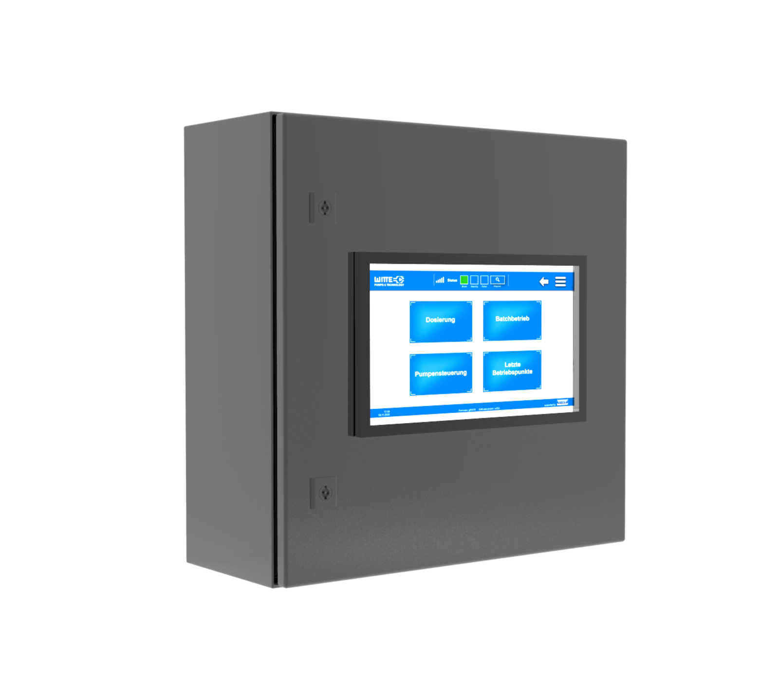
WITTE Core Command - pump controller

From now on, MAAG WITTE also offers the suitable control for its pumps. Together with Blue Automation, a specialist for automation technology, the WITTE Core Command control was developed. This type of control is specially designed for use with WITTE gear pumps, but can also be used with pumps from other manufacturers.

Landscape

The technology

The most modern components were installed in the control system according to the current industry standards. The control itself is based on a Siemens PLC S7. This ensures that in the event of a replacement only the software must be re-read without the need to completely reprogram the control. In case of a defect, the PLC can be exchanged quickly and easily. The operation is carried out via a touch-sensitive 7 inch panel that offers sufficient space to read all necessary information at a glance and to carry out the parameterization comfortably via finger input. 

Landscape

The control system is housed in a small control cabinet that complies with the current industry standard. Due to its small dimensions, it can be flexibly positioned in the immediate vicinity of the pump. The control system is connected to other units such as frequency converters, volume or mass flow meters using conventional industrial plug connections that also comply with current industry standards. An uncomplicated and seamless integration is thus guaranteed and can be realized with minimum effort.  


Dashboard

To keep track of all parameters and configurations, as well as the current state of the system, a tidy and clear dashboard interface was chosen. This is intuitive to use and can be provided in different languages. On the dashboard or via the user interface, all important information can be read off in a good and clearly structured manner.   

In the current operating status mode, the user can view the current pump speed, the flow rate, the output pressure or wear warnings at any time.


Datalogging

The control system also has a data logging function that records the pump speed, flow rate and output pressure during the entire operation. In this way, the history can be used to reconstruct where problems may have occurred. This is particularly important if the pump is used to run different batches. If a deviation occurs during operation, it can be precisely assigned to a batch by means of data logging and, if necessary, sorted out or checked.


Error log

The integrated error log makes troubleshooting fast and convenient. If a problem exists, the user is immediately informed via the user interface and can react accordingly to the displayed error.

Operational safety

The system is designed for maximum operational safety and can be configured so that automatic shutdown takes place on the basis of predefined limit values. In addition, limits for warnings can be defined so that the operator is informed about critical operating conditions even before an automatic shutdown. The emergency stop function is permanently integrated in the software and can be triggered on various parameters such as pressure or efficiency.

Landscape

Interfaces

The integration and smooth integration into existing systems is guaranteed by a variety of possible interfaces. For example, it is possible to optionally connect the control to an industrial bus.

Advantages of the control

The goal was to develop an easy-to-use interface with a wide range of functions that includes all the necessary features for regular operation. In order to ensure the usual flexibility for our customers, care was taken to make a large number of additional options available. With the new control system, the operator has all the operating data of the pump at a glance and can also integrate it directly into his control station if desired.

Signal input

To make the controller usable for the widest possible range of applications, it is compatible with the most common input signals and can process them without any problems. For example, a scalable analog input is available for operation with a volume flow or mass flow meter. If operation in combination with a spindle or gear meter is desired, this signal can be recorded via the separate meter input. When controlling via a pressure sensor, this signal can be picked up via another scalable analog interface. An Ethernet interface also offers the possibility of processing the motor values, such as the speed, via an external frequency converter. 

Signal output

For the exchange with an externally switched frequency converter, the control offers an Ethernet interface in the standard version. However, this can also be optionally extended by an analog interface. 

Signal input

  • 4-20mA
  • 0-10Volt
  • Pulse
  • +24VDC power supply (1A max.)
  • 0 VDC/Grnd

Signal output

  • 4-20mA
  • 0-10Volt
  • +24 VDC power supply (1A max.)
  • 0 VDC/Grnd

Additional sensor

  • 4-20mA
  • 0-10Volt
  • +24VDC power supply (1A max.)
  • 0 VDC/Grnd
Landscape

Features:

  • Direct speed control for pump
  • Control to flow with external flow sensor
  • Control on additional sensor
  • Batch operation
  • Wear warning
  • Error handling
  • Data logging
  • Control via PC/ Software update
  • Optional: EX version, connection to industrial bus